
Remember that three watt led module I built a while back? Well, I finally got around to building a driver/interface for it so I can use it with my rgb led controller.
The time has come!
Specs:
Three LM317T adjustable voltage regulators, configured in constant current variable voltage mode.
Six one-watt 10 ohm resistors, wired in parallel for 5 ohm loads on the adjust pin of the regulator.
Three 1uF smoothing capacitors on the regulator output, one 100nF filter capacitor on the power connection.
Each channel is configured for 250 mA, which is 100 ma less than my leds can handle, but, this is good enough for a start – I have proper sized resistors on order. I will probably make a PCB for the second iteration of this project, and I’ll be using a single resistor instead of two in parallel.
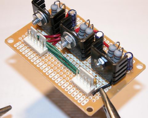
The six pin connector goes to the LED module, the five pin connector is the power and control lines from my rgb led controller.
I started out by laying out the three biggest components of the project, and getting them secured to the protoboard. I’m using a protoboard with two supply busses on it, they’ll come in handy for carrying nearly an amp of current to my regulators. You can see the Vin pins of the regulators all bent ‘up’, overlapping the central power bus.

Now for some resistors. These resistors set the current output based on voltage on the adjust pin. You can clearly see two 10 ohms resistors. I have wired these in parallel, giving me a result of 5 ohms, which sets the drive current at 0.250 A
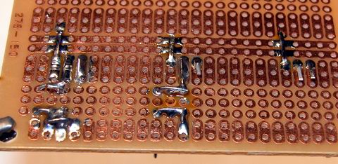
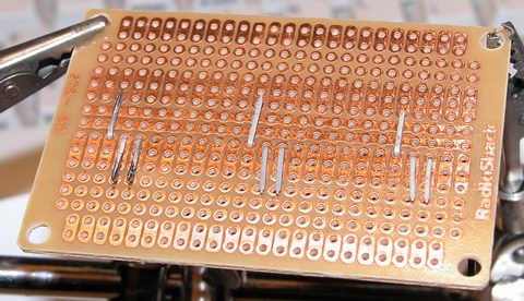
The beginning of the soldering; tacking parts down one at a time.
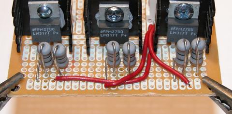
These three red wires each carry the drive current for one color, red, green and blue to the led module connector.

Same wires, different angle!
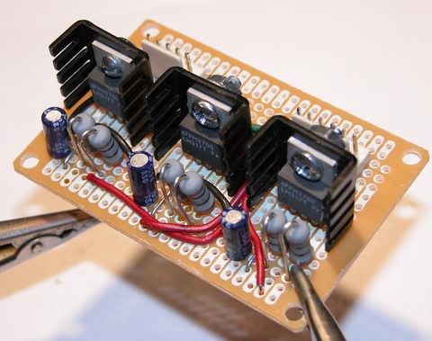
I’ve installed some 1uf smoothing capacitors and a 100nF filter capacitor as per the LM317T datasheet… they help make the leds fade smoother under PWM control.
I’ve got a haloween task planned for this driver, stay tuned!