
I have a running thread over at the linear1 forums, chronicling my experiences with building a digital switch mode power supply.
Here is a re-cap of where I’m at now.
The boost converter is a coil, a few capacitors, a diode and a darlington transistor. The PIC manages switching the transistor. Switching is done autonomously by a PWM generator inside the PIC. Constant current regulation is achieved by measuring the voltage drop across a 100 ohm resistor. The voltage is measured approximately 5000 times a second, and the pwm duty cycle is adjusted up or down, depending on the read voltage’s deviation from the set voltage. With a 100 ohm resistor, the math works out real easy – 100mV is 1 mA. Of course, 100 ohms will not work for a heavy current load – so I will have to reduce it to 1 ohm or 0.5 ohms, which changes my math a little, but no big deal.
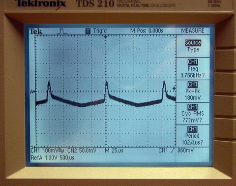
I’m having problems with noise in the output current corrupting the A2D input to the pic. Better capacitors and a real ‘power’ inductor are on order and should arrive wed or thur. When they get here, I will rebuild this project so I don’t have, for example, a 12″ piece of wire connecting my switch to my pwm output.