
Here are a few pictures of my boost-mode converter, originally posted in my thread on linear1.
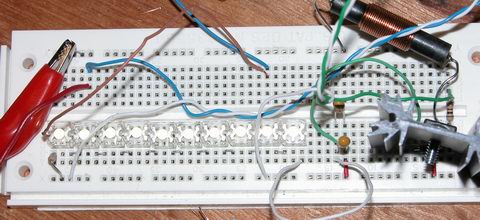
breadboard with 10 led series string, and boost converter circuit
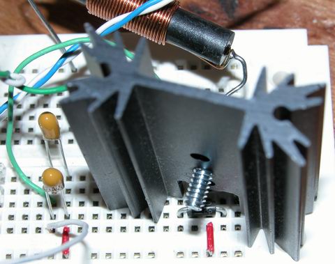
just the boost converter circuit – here you see the output capacitors, the rectifier (buried under the heatsink), the switch (on the other side of the heatsink) and the inductor

this is the pwm pulsetrain from the PIC … only 10khz and already not quite square – it looks a lot worse at 20khz
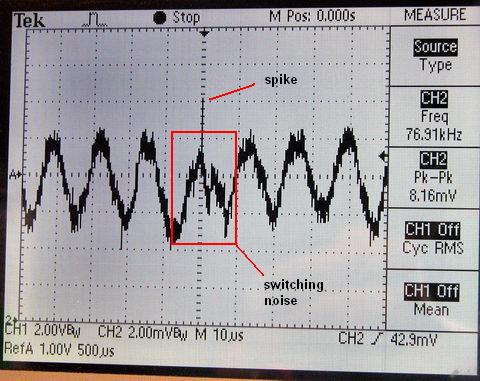
output current measured across a 10 ohm resistor, with a basic choke filter on the output from the converter.