
My previous dead bug attempts were just that, dead bugs … although the mounting method was successfull, it was really difficult to get the chip to stay put – the heat from soldering the connections melted the glue and the thing was sliding around.
So, I made up some PCB layouts for an SOT adapter, allowing me to solder the chip properly, and still provide something I can use easily in a breadboard. This is what I came up with:
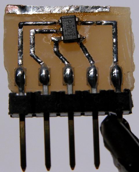
Not the cleanest example of my work, I admit to the fact it looks pretty awful. But it does work well. It is just a simple SOT-23-5 transistor pad layout, expanded to 0.100″ pitch pads. To the big pads, I solder the short side of a molex C-Grid pin header, and then solder the IC to its pads. The C-Grid pins plug perfectly into a breadboard. The whole thing is about the size of a nickel.
Ok, so now that I have the IC in a managable package, what does it do? The IC is a Texas Instruments TPS61040 step-up dc-dc converter. You feed it a low voltage (3 to 6v), and it produces a high voltage (3 to 28v). The IC contains almost all the parts of a switch mode power supply, including the switch itself.

Add a hand wound inductor, a few caps and a schottky diode, and I have a complete SMPS. The 040 offers a few neat features, including analog and digital dimming support, automatic softstart to limit inrush current, open load detection, and very very low standby / no load currents. For my experiments, I decided to power eight white piranha LEDs at 50mA (the 040 can handle up to 400mA). My power source was two 1.5 volt alkaline batteries, connected in series.

I was able to run the leds for a few hours until my super cheap “Shazam” brand batteries gave out. I’m sure with a proper set of four NiMH batteries, the LEDs would run for a long time.
My next experiment will be to run a string of power leds using this converter… say four 2 watt jupiters (well, at 400mA, I won’t achieve quite 2 watts). I need to get a proper inductor and a larger output capacitor, to handle the much increased load.