
Testing SMD devices on a breadboard requires some sort of carrier. You can use the dead-bug method, affixing the smd to something, and using bits of wire to solder its tiny pins to larger ones that fit into a breadboard. Another method is using SMD converters, which is fine, but really limits what you can do with the chip, it’s not very portable, and it takes up a LOT of room for very little gain. So, I decided to try re-drawing some of my designs to fit in the footprint of a DIP style package, but be more or less self contained. These self contained modules will work on a breadboard, protoboard or where-ever.
Today’s theme is switchmode power supplies. To start, here is a ‘single cell’ to +5v boost regulator, based on National LM2698. This circuit should accept as little as 2.2 volts and provide a solid five volt output. With 3.6 volts in, it should provide over one amp of current. Thanks to the large capacitors, this module resembles a 28 pin ‘wide’ dip, approximately 600 mil across.
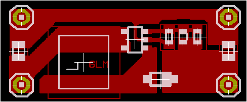
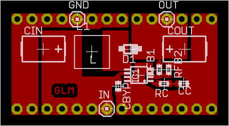
This module is also a ‘single cell’ to +5v boost regulator, based on the petite TPS61040 from Texas Instruments. The chip claims to support voltages as low as 0.9v, but I plan to use it with a single 1.5v AA. The amount of current it will provide is somewhere around 100mA. It can provide up to 500mA using a higher input voltage. This module resembles a 20 pin ‘narrow’ dip, or approximately 300 mil across.

Lastly, this is the smallest design yet. This module resembles a 16 pin ‘narrow’ dip. Also based on TI’s tps61040, this switcher is configured in constant current mode. My prototype design sources 50mA at 23 volts into a string of white LEDs, powered by two AA batteries.