
This is the second incarnation of my tps61040 based LED driver (here and here). As I wrote just a few posts ago, I’m trying out a new layout strategy to make my gizmos more breadboard friendly.
The 300 mil (thanks Dave) DIP16 package proves to be very small, so small I had trouble trimming it completely while depanelizing.
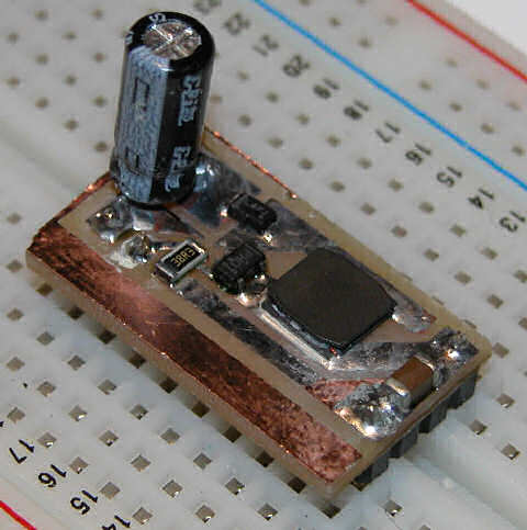
Another problem I ran into is a high voltage output cap. Seeing that this circuit generates upwards of 28 volts, the typical inexpensive ceramic or tantalum capacitors just don’t have the dielectric strength to work well. So, that leaves few options. Option one involves parallel smaller value high voltage caps. I ordered a bunch of 50v 1uF 0603 caps, so we’ll see how that goes. Second option is electrolytic. Sure I’ll incur some losses in the capacitor, dipping the efficiency a bit, but hey, it’s not a perfect world. I found some 10uf 4.3mm x 4mm caps that should do nicely. Third option is expensive ceramic … weighing in at $1 to $5 ea, these caps must be made of lunar rock. I have not ordered any of these, but I will look into harvesting some from dead / old electronics.
Notice the cute little inductor. That baby is 10uH, 1 amp, shielded and only 6mm square. Designed for high power applications, it has a generous saturation current, and rather low resistance. Even better, it’s only like 2mm tall, and to top it off is the cost; 59 cents each at quantity 10. In case you’re looking for an easy to use and flexible inductor, the digi-key catalog number is 587-1707-1-ND.
This time, in order to have a simple board layout, I chose to permanently enable the chip, so they’re be no dimming on this version. I’m not sure if the chip supports a hot load disconnect, I did manage to kill my earlier prototype somehow, one of the output leads broke off the pcb while I was holding it, in a dark room. After repairing the damage, I only get a very low output. Perhaps my capacitor or diode was fried.
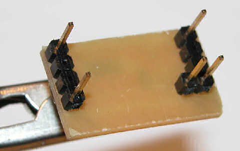
Here are the breadboard compatible pins. The three pins are the output area, with the one inboard pin being the led sink, where the current sensing resistor is attached. This layout required two ground pins, and an external jumper to connect them. I’ll remedy that in the next iteration.
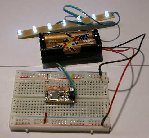
This is the little critter doing it’s thing. Do you like that battery brand? SHAZZAM – it just screams power. I bought a BUNCH of these at a traveling tool sale show, 99 cents for 16. They’re not half bad for light loads, this little switcher sucks ’em dry in a mater of hours however!