
I’ve been working with a new design these past few days … I’m trying to build a portable power supply / charger for mobile usb devices. Inspired by Lady Ada’s Minty Boost, I set out to build something a bit more powerful. Perhaps I can call it the Minty XL? Alas, that is not the topic of this article. The charger is based on two “modules” which are discussed here. I felt it was a good idea to build these modules as separate units, so I can breadboard them and test out their design, before committing to have a PCB professionally fabricated for the actual charger.
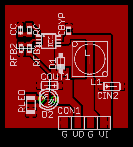
The first module is a boost converter based on the National Semiconductor LM2698. This converter takes 3.6v from the batteries and boosts it to 5v. The converter should supply at least one amp and perhaps as much as 1.3 amps under ideal conditions. To test the design and layout, I’ve designed a small single sided PCB that will plug into a breadboard using a four pin header.
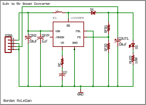
National supplies the LM2698 as a mini-so8 package, so it’ll be some challenging soldering to do with an iron! Although a 4 pin header was used, there are really only 3 connections. Vi will connect to the batteries or current limiting circuit simulating batteries. Vo is the boost output, which is also indicated by an LED. Two low esr tantalum capacitors provide input and output filtering and some smaller ceramic caps provide decoupling for the IC and a filter for loop compensation. Two resistors form a voltage divider, supplying 1.25v to the feedback circuit of the chip. The coil is a two amp 7mmx7mm shielded ferrite core inductor and the switching diode is just some schottky I picked out of the Digikey catalog.
What good is a powerful portable charger if its own batteries wear down? The second module for my project is a battery charger based on Maxim’s MAX1811 Li+ Charger. The MAX1811 is designed to be a USB powered charger, which seems a fitting complement to a portable USB charger. In fact, if you visit a dimension were conventional physics don’t apply, the device may be able to recharge itself! Anyway, the MAX1811 based circuit is very simple – the chip does all the heavy lifting of monitoring the cell health, temperature and state of charge.

Two capacitors, neither strictly required provide filtering on the input and output of the chip. An on-board LED indicates the charging mode. When the LED is on, the charger is bulk charging the cell, up to 500mA. When the LED is off, the charger is either preconditioning the cell (for severely discharged cells), maintaining the cell, or off. I would have preferred a little more information, but hey, I like simple and this chip is that, the blocking diode is even built in!
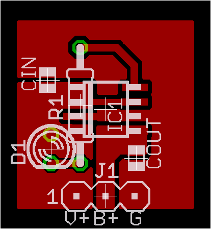
Thankfully Maxim supplies the MAX1811 in an so8 package, so it should be fairly easy to solder. This small circuit board also plugs into a breadboard using a three pin header. V+ supplies the charger with roughly four to six volts. B+ is the charger output to the battery, and both the battery and supply share a common ground.
Hopefully this weekend I’ll be able to fabricate these circuit-boards and will toss up a few pictures of the finished product.