I might be close…

Wow, a long time with no posts – sorry about that!

I have been busy the past week, I wanted to take Thursday and Friday off, so I had to cram a weeks worth of work into the first three days.

I’ve also been racking my brain, trying to figure out how I can integrate a matrix wired LED array into my sensor project. I think I’ve come up with a solution, partly hardware, partly software. Originally I had wanted to have all the LEDs on, and turn them off to do a measurement. This created a lot of problems, mostly due to the current demands. Well, I think I can achieve the same goals, without having all the LEDs lit simultaneously, which will reduce the current demands and should simply the circuit a little.

led matrix sensor array 74hc595

There is the PCB layout for my latest design… I think I’ll make one to test out, and if it doesn’t work for my sensor array, I can use it as a mini marquee. Sixteen vertical columns, anode connected, each driven by a 74HC595 serial shift register. Seven horizontal rows, cathode connected, each driven directly by the PIC’s analog input / digital output pins. To keep current demands low, I will only illuminate one column at a time. I think that still exceeds the design recommendations of the 595, but heck, its all I can think of at the moment.

More than a few days…

More than a few days have passed since my last posting. What have I been working on? Well, the same stuff.

I’d been getting my a** kicked by a logic gate thingy for two days, and turns out, all I had was two wires transposed – ahh well. Here is a re-post of a thread I started on linear1.org:

As part of my continuing effort to develop LED sensor technology, I’ve been trying to tackle the problem of expansion… My original brute-force method was an army of PIC microcontrollers, discretely controlling individual LEDs. While this method worked and was rather simple from a hardware stand-point, there were several drawbacks. The most ADC ports I was able to use was ten… there are microcontrollers with more than this, however they have certain drawbacks that make them unsuitable for my application. Knowing the limit of 10 leds per slave, to build an array of a useful size, say 3×10, would require three slave microcontrollers. Although not enormously expensive, each mcu costs at minimum $3, which adds up quickly.

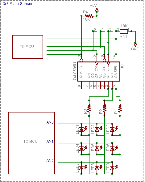
The method I am currently exploring involves linear logic chips, specificly the 74HCT595N 8 bit serial load latching shift register. Here is the idea, and I’ll throw up a schematic shortly. The cost of a 595 for hobby purposes is roughly 75 cents. Even a modest quanity of 20-25 shifts that price down below 50 cents a piece. Far better than the cost of individual microcontrollers.

The 595 is used to source current, driving the anode axis of the array (columns). I fill the register with 1’s, which sets each output as a current source. While filling with 1’s, I clear the bit for the column which contains the LED I want to sample. The 595 holds this state indeffinately, until it is changed by the microcontroller. The microcontroller, which is directly interfacing the cathode axis of the array (rows), then samples each LED in that column by applying a reverse bias charge and then switching to a high-z input for the A2D reading for each row. This is done one bit at a time (each bit equals a row), so neighboring rows are left “on” at are lit, allowing a good amount of light to be reflected into the led currently being read.

This new arrangement allows a single microcontroller to handle a matrix of ‘unlimited’ columns by ten rows (each row needs to be connected directly to the microcontrollers unique tri-state IO port). A 160 pixel array of 16 columns by 10 rows needs only one microcontroller and two shift registers. Of course, the actual size of the array will be determined by how fast the PIC can scan through the columns, since one column is always ‘dark’ to allow for the reverse bias and read operations. Currently my microcontroller can scan my 3×3 array at a rate of 27kHz, which gives me a WIDE margin, since anything over 70 hz is practically impreceivable.

There are some flaws I need to sort out, mainly power related. The 595 can source 35mA and sink 75mA. 35mA is fine for a 3×3 array, but it won’t cut it for anything much larger. I need to find a way to increase the current handling abilities of each port, without a huge component count or complexity. If I build an array with 10 rows, each column needs to source 200 mA of current. But it also needs to retain the ability to sink a small amount of current. I figure I can solve this with a pair of transistors, one small npn for sinking, one larger pnp for sourcing.

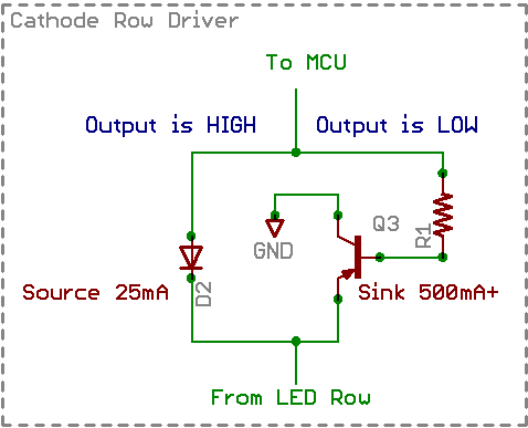
Secondly, my microcontroller can source 25mA of current which is more than enough to reverse bias an led quickly, but it can only sink 35mA of current. So, when sinking a row that may be 16 or more columns long (at 20mA per led), some serious power handling capacity comes into play here. A simple TO92 mosfet can sink an amp of current without breaking a sweat, but I also need the ability to source current and the ability to go “high-z” to allow the microcontrollers internal circuitry to do the A2D sampling.

I think I am close to lickin this issue. More to come.

More LEDs, Less SLAVEs

Well, I’m having a some code-writers-block on applying data from the array to anything usefull… so I’m looking at ways to get more data from fewer and cheaper microcontrollers.

The cornerstone of led sensing is tristate logic. The PIC microcontroller can set each of its pins to high, low or neither (high-z). This is what allows me to forward bias, reverse bias and then sample the led. However, doing all of this requires a large number of pins on the PIC. Two pins are required for each LED. That’s why I did all this work on networking pics on a shared bus… but the cost of pics is pretty extreme, so I’m wondering about alternate ways of accomplishing the same.

Enter low-cost analog and logic interface ICs. There is a device called the 74HC573 octal tristate latching buffer. Basicly its a chip with 8 outputs, which can be high, low or high-z — same as the PIC. I really don’t care about the number of outputs, I plan to use a pair of them in an all or nothing configuration… tie all the data input lines together with a single PIC pin. I also probably won’t need the latching ability, but the 573 was cheaper than the 244 which is an octal driver without latching. So, the pic can control 16 led anodes with 1 pin – thats some awesome savings right there! 🙂 Next comes the cathode side, which is what the PIC reads with the ADC. For driving the cathodes, I plan to use the same configuration as the anodes, with the exception that I’ll also use the output enable line on the 573, to put the outputs into high-z just before sampling. All this leaves is the actual sampling. I’ll do this with a 16 to 1 analog multiplexer. The mux has a pretty high RDS(ON), something like 180 Ω … which is actually pretty close to the 150 Ω I’m using now. I figure I can put my resistor on the cathode side, after the mux connection, so when the cathode side driver is in high-z mode, my current limiting resistor disappears. In order to keep the array bright and eliminate any humans from seeing flickering, I’ll flash the entire row before sampling each LED. This should also give me the best conversion resolution on my leds, since the sampling time needs to be so high, I wouldn’t be able to read them all before their values changed.

By my calculations, scribbling in notepad, I figure I’ll need nine lines from the pic to control 32 LED lines (anodes and cathodes for 16 leds). Which is great, since I can use the lower-priced 18pin PICs… and it also sets the default row size to 16, up from the current 10. Of course, there’s no reason I’d need to do the full 16, but its good to have options! For the cost of one more pin from the pic (still easily within the 18 pin range), I could add another 16:1 mux, and lay 32 leds on a single pic! With the pic able to source and sink at least 25mA; it should be able to drive a ton of 74HC573s, which according to the datasheet need 1μA of input current per data line. Muhahahah! I’m not sure how many LEDs each PIC can handle and still have enough time to get a few complete collections inbetween servicing i2c interrupt requests with a 400 or 1000 khz bus clock.

LED Sensors III

After stuggling in the mud for the past week or so with compiler issues, I’ve finally broken free!

I have a newly configured breadboard, with enough room for four slave ICs, each handling ten LEDs. I haven’t found a decent way to create more than a double row of leds, given the way a breadboard is laid out electrically. I fear I’ll be making some PCBs for this endeavour shortly.

I’ve come up with a neat bit of code to set the address on my slaves, using a single pin. With one pin, I can actually set up to 127 different addresses, however I’ve got it capped at 16 for now. A buddy of mine suggested the idea of using diodes as or gates, for reading a bit shifted across the 8-bit port on the pic. So with between 0 and 4 diodes as a mutliple input single output OR gate, I can read any binary number between 0 and 15 (0000 to 1111) with a single pin, which happens to be the only one left!

I’ve also found the hundreds of cheap’o LEDs I ordered from a popular auction site aren’t well suited to this application. I believe this is because of their tight lense angle of 20°. The leds I was using prior to this had an angle of 45° and I’m now using heavy-duty piranha leds with an angle of 70°. I’m going to look into getting more of the 45 deg leds, I think that angle offers the best combination of a focused upward beam but still allowing enough off-axis light back in.

I think now that I have the sensors returning data the way I want, I need to work on applications to interpret that data and do something useful with it.

As soon as I remember to recharge my camera battery, I’ll have some more pictures.

Stuck in the mud

Just wanted to write up a quick update on my bi-directional LED project.

I’ve switched to a more ‘fitting’ microcontroller, the pic16f737, which has eleven ADC ports on it, although i’m only able to use ten.

after scaling up my code from four adc to ten adc inputs, and changing a few other things around, I compiled the code for the 737, and loaded it on. The 737 isn’t as nice as the 876a, the biggest drawback is it cannot self-program. Which means I have to use an eeprom programmer every time I want to update the firmware, instead of just flashing the firmware update serially.

Of course, the program initializes OK, but is not sending the data. I’m not sure if it is not reading the data correctly from the ADCs, not passing it into the transmit buffer, or not timing the transmits correctly. Whatever the case, I need to debug. This is where my current problem comes into play. I cannot get any useful data out of the hardware serial port, regardless of how slow a baud rate I choose. It appears to be a problem with my compiler and a recent update. I’m currently exploring that over on another forum.

Needless to say, once I get my debugging output fixed, I’ll be able to quickly (i hope) identify the source of the no-data problem, and be on my way to building a very large led array.

3 Channel Driver

Remember that three watt led module I built a while back? Well, I finally got around to building a driver/interface for it so I can use it with my rgb led controller.

The time has come!

three channel constant current led driver

Specs:

Three LM317T adjustable voltage regulators, configured in constant current variable voltage mode.
Six one-watt 10 ohm resistors, wired in parallel for 5 ohm loads on the adjust pin of the regulator.
Three 1uF smoothing capacitors on the regulator output, one 100nF filter capacitor on the power connection.

Each channel is configured for 250 mA, which is 100 ma less than my leds can handle, but, this is good enough for a start – I have proper sized resistors on order. I will probably make a PCB for the second iteration of this project, and I’ll be using a single resistor instead of two in parallel.

The six pin connector goes to the LED module, the five pin connector is the power and control lines from my rgb led controller.

protoboard solder three channel constant current led driver

I started out by laying out the three biggest components of the project, and getting them secured to the protoboard. I’m using a protoboard with two supply busses on it, they’ll come in handy for carrying nearly an amp of current to my regulators. You can see the Vin pins of the regulators all bent ‘up’, overlapping the central power bus.

one watt resistors lm317 voltage regulator constant current led driver

Now for some resistors. These resistors set the current output based on voltage on the adjust pin. You can clearly see two 10 ohms resistors. I have wired these in parallel, giving me a result of 5 ohms, which sets the drive current at 0.250 A

protoboard solder constant current led driver

The beginning of the soldering; tacking parts down one at a time.

lm317t constant current led driver wiring

These three red wires each carry the drive current for one color, red, green and blue to the led module connector.

three channel constant current led driver molex kk connectors

Same wires, different angle!

three channel constant current led driver LM317T

I’ve installed some 1uf smoothing capacitors and a 100nF filter capacitor as per the LM317T datasheet… they help make the leds fade smoother under PWM control.

I’ve got a haloween task planned for this driver, stay tuned!

LED Sensors II

Having spent only a few hours cooking up the first vb app to talk to my array, I shouldn’t be surprised that its performance was rather lack luster, not to mention the wiggly lines on the bar graph although visually stimulating really offered nothing in terms of interpretation.

visual basic led sensor data analysis

Here is a view of the new application… I’ve re-designed a good deal of the internals, and changed the graph around so it represents more clearly the data being received from the array. Each row in the bargraph represents a row in the array, and the height of each bar indicates the amount of light the sensor is receiving.

So as I interact with the array, the bars follow along.