Down to the wire

Well well well – time is running short, and only one of three outstanding orders has been filled.

The boost converter is coming along – I’ve made refinements to the software that offer some good features and better performance. However, I think my hardware design needs more work… and for that, I need parts!

Out of desperation, I visited Satan’s Lair aka Radio Shack and was pleasantly surprised to find some of the items I had been missing. I managed to get a 2a 100uH inductor and (only) two 1uF tantalum capacitors. Having a proper inductor really made a big difference in the output of my boost converter – it sails to the limit I set for 25mA without any problems now, the old hand wound torrid would struggle to get past 20, begrudgingly giving me 25mA along with a lot of HEAT. The real test will be tonight – I’m going to wire up some power resistors as a test load and see if my boost converter can give me half an amp. Why 0.5A you ask? I need half an amp to drive my Moon LEDs at their fully rated 2w power.

The boost converter was originally intended to be a power supply for two parallel strings of LEDs, installed as under cabinet lights.

The lights themselves will be made of aluminum C channel and plexiglas, using 2 watt IO Moon led modules, spaced evenly along the length. I’m not sure what the spacing should be – there is probably some math that would tell me, based on viewing angle and what not. Since these are a prototype, I’m going to ballpark the spacing, so the LEDs I have (4) are spaced evenly across the length of the countertop. I need to take a few covert measurements to figure out how long the channel needs to be. I managed to find a local source, and have secured sixteen feet of aluminum C channel. This stuff has a chunky 1/8″ wall thickness and 1.5″ x 0.5″ outside measurements… combined with a little Arctic Silver, this should be an awesome heat sink for the LEDs.

Pictures to come shortly!

PIC Based Boost Regulator

I have a running thread over at the linear1 forums, chronicling my experiences with building a digital switch mode power supply.

Here is a re-cap of where I’m at now.

The boost converter is a coil, a few capacitors, a diode and a darlington transistor. The PIC manages switching the transistor. Switching is done autonomously by a PWM generator inside the PIC. Constant current regulation is achieved by measuring the voltage drop across a 100 ohm resistor. The voltage is measured approximately 5000 times a second, and the pwm duty cycle is adjusted up or down, depending on the read voltage’s deviation from the set voltage. With a 100 ohm resistor, the math works out real easy – 100mV is 1 mA. Of course, 100 ohms will not work for a heavy current load – so I will have to reduce it to 1 ohm or 0.5 ohms, which changes my math a little, but no big deal.

oscilloscope digital tds 210 Tektronix current ripple

I’m having problems with noise in the output current corrupting the A2D input to the pic. Better capacitors and a real ‘power’ inductor are on order and should arrive wed or thur. When they get here, I will rebuild this project so I don’t have, for example, a 12″ piece of wire connecting my switch to my pwm output.

PIC Based Boost Converter

The idea of using a PIC microcontroller as a replacement for the analog circuitry of a smps controller was originally suggested to me by SurJector over on the linear1.org forums.

Originally I felt the topic was over my head. I also dismissed it because I thought it added unnessecary complexity to an already difficult to understand process. However, as I read more about how switch mode power supplies and dc/dc converrts worked, I realized that using a PIC as the brain was indeed a good idea, and very cutting edge. ‘Digital’ switch mode power supplies are just now starting to ‘pop up’ in the industry, with all the current “all in one” controllers still relying completely on analog.

As I understand it, a digital controller offers the potentional for great efficiency, by adjusting the operating frequency of the switch dynamicly with the load. I’m not sure how that all works yet, but I have a few other things in mind, related to using these converters in the field of solid state lighting. Firstly, I like the idea of being able to digitally controll the output current to the load. Instead of having to dim a bulb using PWM, which is very non linear, I can instead dim a bulb using current mode control… using whatever interface suits me. Secondly, a digital controller could be integerated into a larger project, an illumination manager. For example, combine the dc/dc conversion routine with a routine reading a thermistor – monitor your bulb temp and dynamicly vary the current to keep it at a safe level. Another possibility – with a digital processor monitoring the current draw of the load, a faults such as shorted or open diode could be detected and an alarm condition set – in addition to reducing the current to compensate, a small indicator led could light up – “Check Lights”.

I have some pictures and schematics to share when I’m back home – more to come!

Dead Bug

In addition to my new moons, I also received some sample DC/DC converters from Texas Instruments. In order to experiement successfully with this new switch-mode power supply, I need to be able to use it on a breadboard.

I could have drawn up and made my own ‘breakout board’ pcbs. I could have bought commerically made ‘experimentor’ boards. But I decided to use the cheap and fast “dead bug” method instead. I used a little dab ‘o hot glue and a 6-pin DIP socket to convert my SOT-23 packaged device into something I can now use with a bread board.

The jumper wires I used are two strands of wire for a 24ga stranded wire. I twisted the two strands together for a little more strenght. I also used some 24 ga solder wire to extend up from each spring in the socket, rather than soldering to the spring itself. The hard part with this process, and I think I’ll look to epoxy instead of hot glue next time – as I heated the part during soldering, it would soften the glue, and the part would move! In the last picture, it looks like there are some solder bridges, but there are not – that crap between the pins is just debris from my parts cleaning brush … looks like its time for a new brush!

More on the TPS61040 and what it does a bit later.

Enjoy:
dead bug solder tps61040 sot-23 smd
6 pin dip socket

dead bug solder tps61040 sot-23 smd
cut tape string of four converters

dead bug solder tps61040 sot-23 smd
single converter sitting on an 8 pin DIP package IC

dead bug solder tps61040 sot-23 smd
converter glued to ic socket

dead bug solder tps61040 sot-23 smd
starting the soldering process

dead bug solder tps61040 sot-23 smd
finished soldering

New Moons

I have a project planned for some high-end under cabinet lights, using 2 watt Nichia Jupiter LEDs. The LEDs are packaged and mounted by LuxDRIVE in their IO Moon product. The IO Moon takes the jupiter LED and has it mounted on a very thin printed circuit board. The pcb is two layer, however, only the top layer is electrically active – the planes on the top and bottom are connected by a bunch of through-plated vias and the bottom plane is not masked, instead it is left as an exposed, tinned surface.

Luxdrive claims the moon can operate at a recommended current of 350mA in ‘free air’ at 25°C ambient. However, to achieve the full 500mA drive current, a heatsink is required.

I have chosen 70° viewing angle lens and a warm-white phosphor. The LED looks very nice, however, I’ve only been able to run it at 1/10th power so far. The color is a big improvement over the very blue common white led.

Here’s some pictures!
luxdrive io moon led jupiter nichia front face

luxdrive io moon led jupiter nichia back face

luxdrive io moon led jupiter nichia profile view

luxdrive io moon led jupiter nichia

luxdrive io moon led jupiter nichia

Rainbow LED Chaser

I was bored this past sunday, and needed something to ease my racing brain … so I picked an easy project with lots of flash.

The parts list:

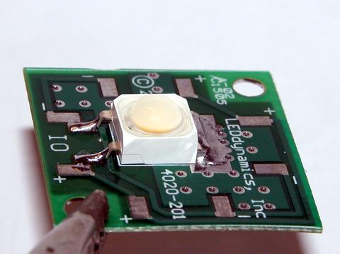
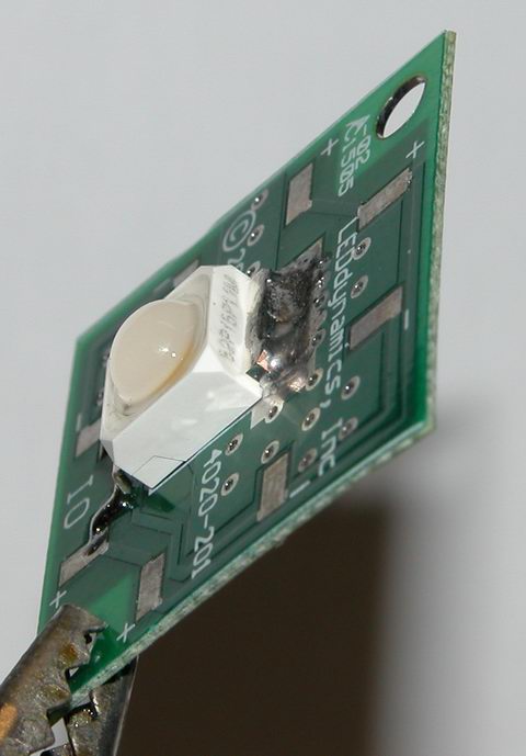
Eight Tri-Color or RGB leds … each led package contains three LEDs
Three 74HC595 Shift Registers … serial load, latching. other varieties would probably work too.
One Microcontroller … doesn’t matter what it is, I used a pic18f252 since it was handy.
Twenty-Four Resistors … I used 150 ohm to set my led current at 20mA, but use anything from 56-220 ohms

The tri-color leds I used are wired as common anode LEDs … each led inside the package has its own cathode pin and shares a common anode pin. So, all my anode pins connect to the postive rail on the breadboard. There’s no reason a person couldn’t use twenty-four discrete LEDs, or eight common cathode leds. Since my leds are “active low”, outputting a 0 turns them on, outputting a 1 turns them off… if you used common cathode leds, they would be “active high”, a 1 would turn them on and a 0 off. If you used discrete leds, well, hook ’em all up one way or the other.

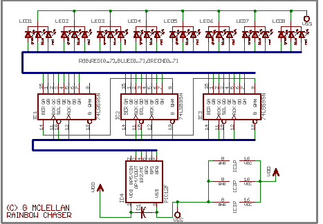
Next comes the connections to the shift registers. Think of each register as a chip containing eight switches you can turn on or off remotely. Each of the 24 LEDs gets connected to an output on the register, and they need to be grouped by color and kept in order. So looking at the picture below, working left to right, I connected all the red leds to the first register, all the blue to the second, all the green to the third. This resulted in the rats nest of wires you see between the chips and the leds. Concerning the registers themselves, they have three connections of up-most importance. Pin seven is the ground connection, pin fourteen is the +5v connection, and pin thirteen is the enable or tri-state pin. The tri-state pin must be tied to ground in order for the outputs on the register to work. Next up is the data connections. The 595 offers a nifty feature of serial pass-through. Using this feature, you can chain a bunch of them together, and treat them as a large number (in the programming). This is done with the QH* and SER pins. QH* connects to SER on the next ic ‘down stream’. On the first IC (the rightmost in my picture), SER connects to the microcontroller. Now in order to ‘load’ the chips with serial data, the microcontroller has generate a ‘clock’ for all the chips to sync to. This clock signal is transmitted on the SCK (serial clock) line. All three SCK lines are wired in parallel to the microcontroller. Last, since we want the data to be retained by the registers, even if the pic stops transmitting, we need to latch the data. This is controlled by the last data line, RCK. When the microcontroller is finished transmitting data, it needs to pulse the latch clock RCK high briefly. Upon receiving this signal, the registers display the data which they just received, and continue to display it until told otherwise. I have some other lines connected, but don’t use them… they are the SCLR line, which clears the data from the buffers, and the enable line. The microcontroller keeps the enable line high (disabling the registers outputs) until it is read to start sending commands… this prevents the registers from powering up with weird random data being displayed.

That’s it for the hardware side … really simple. All the magic happens in software… which I will write about in part two (yes, I’ll post the code too). As a spoiler, all the software does is boolean math, shifting and inverting 8-bit words of 1’s and 0’s around.

Here is the breadboard:
rgb led microcontroller 74hc595 shift register
The parts in the grayed out areas are just stuff left over on the breadboard from an earlier project, or support components for the microcontroller.

Here are some videos:
Initial Testing Video
Center Pulse Effect

UPDATE:
Due to all the connections (24 of them between the registers and the LEDs), drawing a schematic can get messy. I chose to avoid this mess by using Eagle “BUS” feature, which allows a large number of signals to be combined into one wire. The schematic below is drawn using a much less expensive and smaller PIC than the one pictured in the breadboard … however the idea is still the same.

74hc595 shift register microcontroller rgb led chaser

Here is the source code (in BASIC of course) for the “center pulse” effect, it’s pretty much just taking binary patters of 1’s and 0’s and moving them around to create the ‘animation’.

click to download centerpulse.bas

Long Time, No See

Sorry I’ve been neglecting my blog!

I’ve been doing a lot of reading and research, as well as playing with a new toy.

Here are the top-5 items in my current project queue, sorted by priority:

1) LED backlit Rooster Project – Christmas Gift
2) High-End LED under cabinet lights – Christmas Gift
3) Rainbow LED chaser – New Toy / Fun Project
4) LEDs as Sensors – Interface Project
5) LED Matrix Display – 8×8 display modules

I’ll write more about the rainbow chaser tonight (I promise!)… The backlit rooster is just a cheezy Christmas gift I hope to do up cheap for someone who likes roosters and chickens in their kitchen decor. The high-end under cabinet lights are based on Nichia Jupiter LEDs – this project is currently in the very early design stages. I hope to get a proof of concept prototype built by xmas. LED as Sensors is sort-of stuck – I became obsessed with trying to build a large sensor array, but decided today, I don’t need a large sensor array… so I’ll regroup and start a fresh with actual application development for the sensors as I have them now, and worry about building them larger down the road. The LED matrix display will probably never get built, I just had some fun drawing up the designs… Once I priced out the cost to build them, my interest diminished (64 super flux LEDs for each module, 10-16 modules for a good sized display!).

Iron in the Fire II

In my previous post, I write about an LED matrix for a marquee. The display itself is a two-board solution, the second board or ‘daughterboard’ piggy-backs on some pin headers from the display board. This second PCB provides the control interface and logic for handling these 64 leds, and passing along control data to any upstream displays.

led matrix display schematic diagram

The controller uses a 595 shift register to provide the ON/OFF control for each of the eight columns. To provide maximum current to these columns, I have used the ULN2803 current-sink driver. The 2803 is basiclly a darlington array which uses a small current to sink up to 500mA, on each channel… and it has 8 channels. So if I really blast my piranha LEDs with their bleeding edge maximum current of 80mA and the data called for all eight columns to be active at once, the entire column would need a total sink of 640mA! I believe the 595 alone can only sink 200mA. The daughterboard has no circuitry on it for controlling the rows of the matrix – they are just wired in parallel to the daisy chain connectors, which will connect it to a current source on the ‘master control’ or interface board. I plan to use some P-Channel mosfets to handle sourcing potentionally several amps of current. For example, if I connect sixteen of these modules together, and want to turn an entire row on at once, that is 128 LEDs, each drawing 80mA, for a grand total of 10.24A. Wow, that is a lot of power, my goodness, good thing I have a bunch of old AT style switching power supplies laying around, with 15-20A on their 5v rails.

The 595 shift register is just a set of switches, which are set through a synchronous serial interface – a big long string of 1’s and 0’s is clocked out of whatever ends up controlling this marquee (most likely a PIC microcontroller). Each register takes eight bits, thats why I went with eight columns. So if I build a sign with sixteen of these modules, I’ll be pushing 128 bits out a serial port. The entire register will need to be updated for every row, so an entire refresh will take 128 * 8 bits or 1024 bits. At 20mHz, my pic can clock a bit out every two microseconds, so refreshing the entire marquee would take roughly 2.1 milliseconds. A frame rate of 30FPS should be entirely possible, since 1/30th of a second is approximately 33 mS, that leaves a LOT of extra time for the pic to take a nap with… and if I go crazy and build some huge mother of an array, I can beef the pic up to 48mHz, hammering those bits out more than twice as fast.

The display modules are ‘modular’. Daisy-chain connectors provide pass-through of the row current, and data-control signals from the microcontroller. The D-IN port connects the ‘upstream’ registers serial output (QH*) to the current registers serial input (SER), the D-OUT port connects this registers serial output to the next registers input. The rest of the signals are straight parallel. Only changes in the software of the microcontroller would be required to add or subtract display modules from the finished array.

The pcb design and layout is ‘diy compatible’ I’ve used all through-hole components, and jumpers instead of via’s. If I send these out to be fabbed, I’ll probably change the signal routing around, switching the jumpers to vias, perhaps I’ll go with smt ICs, depends on how the layout works out… I might keep the through-hole because I like being able to run signals between the pins and under the ICs, which is hard to do when they’re tiny! The notations “dont move” are just to remind myself (or anyone else) that you can’t move the ARx (anode row) and CGx (column group) connectors, because they’re specificly positioned to mate with the display board.

composite pcb layout image
composite image of controller layout and top+bottom layers.

same disclaimer as my earlier post, these designs and images are not public domain… please read the disclaimer in my earlier post.

A New Iron for the Fire

I didn’t get a chance to make any PCBs this weekend, actually had more fun drawing them. I’m kinda stuck on my LED sensors project, since I haven’t come up with a good way to handle the current demands of an array yet, the catch is being able to reverse bias the rows/columns/whatever. so, I’ve been looking at building an led marquee instead. I’ve learned a lot about multiplexing and scanned LED matrices and arrays, and think it would be a good diversion.

There are a lot of pre-fab matrices out there, but the bright ones are expensive (for good reason I suppose), and what’s the fun in buying something pre-fab anyway. I’m thinking about using white piranha, but maybe green (red and blue have been done to death). The pulsed current specs on the white piranha I’m looking at show a max of ~80mA, with ~60mA being the close to the 200mW rating and 30mA being the continous wave rating (100mW). I have yet to do the math yet to make sure I stay within the pulsed current duration of 1mS max, but it shouldn’t be a problem.

I designed the PCB to be a huge heatsink, with almost all the copper left intact on both sides. This matrix is wired as cathode column, anonde row. Each column is driven by a darlington on the daughterboard (more on this in my next post). Each row of the completed array will be driven by some beefy P-Channel MOSFETs. To facilitate the mounting of the daughterboard, which piggy-backs on the display board, I used some standard .100″ spaced pin headers, seen as CG1-4 and AR1-8 (column ground and anode row.)

The top, bottom and layout art are linked below to full-scale TIFF images, for making your own PCB. I also have a for a multi-layer image in the Paintshop Pro format, which has the top and bottom layers on a 100x150mm 300dpi layout, for making transparencies to use with small double sided pcb’s I have.

Here is a not-to-scale composite image of the layout and top+bottom sides for what I call the ‘display board’:
printed circuit board layout leds

This is the schematic diagram of the LED array, showing the 64 indiv. LEDs and the connectors… linked to a larger version:
led matrix schematic diagram

Here are TIFF format files of the various artwork layers at 300DPI:
Display Board PCB, Bottom Layer
Display Board PCB, Top Layer
Display Board Parts Layout
Control Board PCB, Bottom Layer
Control Board PCB, Top Layer
Control Board Parts Layout

** Note: Paintshop Pro Image Format!
Double Sided PCB Layout, one display, one control, plus some stuff for another project.

Please note, these designs, layouts, pictures, etc are not being released into the public domain. I reserve all rights as the creator and copyright holder. I do however permit the hobbiest to use these designs in their own not-for-profit projects as they see fit. I also permit redistribution of the design and images by hobbiests for the purposes of education and other not-for-profit uses. Please mention me and/or give a link back here if you post these on another website.

EAGLE Libraries

Turns out, I didn’t get to make any PCBs over my four day weekend. I did spend a lot of time drawing things.

I have some parts libraries to share with everyone, I tried asking on a very popular electronics forum for the LED displays, but no one wanted to share, so I had to re-invent the wheel. Trusty caliper in hand, I measured the packages, and transfered those measurements to my cad program. The package for the 2 inch led matrix is dead on, I’m not 100% certain on the 0.7 inch matrix, I didn’t test it as much… the pins are fine, but the footprint might be a little off. By the way, these parts libraries are for Cadsoft Eagle.

LED Matrix Displays

High Flux ‘Piranha’ LEDs

Note; about the piranha package – the through hole layout is OK, the smd layout is brand new and probably needs a little refinement, but lines up good.