Temporary Lights

Another of my hobbies is keeping freshwater tropical fish. Ever since moving into my new house, and building my electronics lab upstairs, I haven’t been too interested in the fish. I give them more water when they need it, feed them on occassion, and do minimal basic maintainence.

The 55 gallon tank has gotten quite out of hand. A single variety of cryptocorne had gone on a killing spree, and had consumed the entire floor of the tank, wiping out every other plant that was in there. After it had consumed all there was to consume, fate turned the tides, and algae began to consume the crypts. So, with much disgust, I threw away all the crypts (mostly all covered with algae)… along with them went most of my substrate, entangled in the massively thick root balls of the crypts. So now my 55g sits empty – except for the fish, some huge snails, and the ugly life support equipment.

The tank normally has 108 watts of T5HO lighting (excessive for fw) , however, without any vegatative competition, algae would quickly rule the roost had I maintained normal lighting. So, I thought this would be a good application for LED lighting. The weak, sickly glow from “white” piranha leds will give me enough light to see my fish, and keep them accustomed to a day/night cycle, but not enough for algae to survive on.

piranha superflux LED strip

My solution involves 24 white piranha leds, with a color temp somewhere around 5000 kelvin. The 24 leds are broke up into four strips of six, those four strips wired in parallel across the power supply. The power supply is a LM317T wired up as a constant current regulator.

piranha superflux LED strip

The strips are designed with basic thermal management in mind. Since I am running the piranha at nearly 150mW, they generate a fair amount of heat. Therefore, I designed the strips with a maximum amount of copper possible, to act as heatsink and radiator.

pcb artwork superflux LED strip

All together, the ‘fixture’ consumes a little over 4 watts of energy. Here is the basic schematic of how things are wired up. This design is not very ‘safe’ … should an led strip fail as an open, the regulator will provide too much current to the remaining strips. The addition of a transistor and resistor to each strip would help combat this problem, by switching the current programming resistor in and out of the circuit… but this would require me to re-draw everything, make new PCBs, etc etc. This solution only needs to last a few months, once warmer weather arrives, I’ll be mail ordering some plants and have the tank restocked and the main lights working again.

superflux LED schematic diagram

LED Drivers

One of the “quests” I have been on lately, is to find an optimal solution for driving Light Emitting Diodes. I want a solution that balances three key needs; efficiency, flexibility and cost. Efficiency and cost have a direct linear relationship it seems – the more efficient something is, the more it will cost. Flexibility seems to have an inverse relationship with efficiency – the more flexible a solution is the less efficient.

For example, take these three basic “led driver” prototype circuits:
led driver prototypical schematics

Starting off, the plain ‘ol resistor. The only strength this solution has is cost. It is neither flexible nor efficient. That is not to say an optimally designed solution will not see decent efficiency using a plain resistor, the designer needs to closely match the LEDs forward voltage to that of the supply. Now as long as the supply voltage never changes and the attributes of the LEDs never change, the resistor will do its job, limiting current. However, if the designer has limited control over the supply voltage, the resistor’s efficiency is down the drain. Because a resistor is a passive component, it cannot react at all to any changes – therefore the designer needs to specify a resistor for the maximum anticipated supply voltage, which results in sub-optimal light output during periods when the supply voltage is less than maximum. Low efficiency equates to wasted power and excessive heat. In summary, the plain ‘ol resistor is the easiest ‘driver’ to build, using simple arithmetic, the value and capacity of the resistor can be calculated; R = (Vsupply – Vleds) / Ileds and P = Ileds ^ 2 * R.

Next, we have the humble linear regulator. I chose the LM317, which is widely available and very inexpensive. The strengths of linear regulation are two fold. First, linear regulation provides a wide degree of flexibility. Secondly, linear regulation provides a very low cost. Two out of three is not bad, but the last one is the kicker. Linear regulation is terribly inefficient. A linear regulator configured for constant current mode is going to consume (dissipate) almost as much power as the load it is regulating. This means a 5 watt LED load is going to have the regulator dissipating an additional 5 watts. So using linear regulation in your design, the power source must deliver 10 watts to give yeild 5 watts of power for the lights, and this is an optimistic 50% efficiency – National Semiconductor gives the LM317 something like 43% efficiency! In summary, the linear regulator is marginally more complex than using a simple resistor, and about as easy to design. A single equation gets us the value of Rs, the current sense resistor; Rs = 1.25 / I.

Next we have the compound, pre-made group of devices that I call switchmode drivers. The switchmode driver is a ‘black box’, in its simplest form, offering four leads, two inputs, two outputs. Drivers are available in two primary configurations; step up (boost topology) and step down (buck topology). Both configurations excel in efficiency. While efficiency alone is a good enough reason for some designs, such as battery powered applications, the switchmode drivers also offer a limited degree of flexibility. The negative aspect of a switchmode driver is cost. Prices for switchmode drivers start in the neighborhood of $10 and top out around $60. Flexibility in switchmode drivers is usually in the form of allowable ranges. For example, a step down driver may allow an input range Vout + 2V to 36V. That same driver may also have a range on the output, for example 3V to 28V. The biggest drawback to the switchmode driver is the lack of adjustable drive current. In general, a switchmode driver has to be purchased from the factory with a pre-programmed drive current. While this is fine for most designs, it is not optimal. In summary, the switchmode driver offers excellent efficiency, often times better than 85%, but it offers this efficiency with great cost and limited flexibility. There is no math required to design using a switchmode driver, you just have to pick one that matches your supply voltage and LED current needs.

The last driver I will briefly touch on, saving the details for next time, is the home-brew or DIY switchmode driver. In kit form, this driver satisfies all three of my design goals. Decently low cost (less than $10 in parts), high efficiency (more than 80%) and good flexibility (I control the programming). Of course, there are some drawbacks; some of the parts are hard to find, there is a LOT of math involved and due to high frequencies and currents, careful circuit layout needs to be observed.

Another technology I will mention, but have not researched much (it is truly bleeding edge in the industry) is something called SEPIC. The acronym stands for Single Ended Primary Inductor Converter. It is a technology pioneered by Maxim and combines the abilities of both a step up and step down regulator into a single design. The ‘old fashioned’ buck-boost regulator of yesteryear do their voodoo by internally generating very high voltages, and using the positive rail as a low side reference for the load … that design has some very hard limits and is also rather inefficient. SEPIC hopes to solve these problems with a radically different and more complex design. SEPIC offers a power supply that with ultimate in flexibility – there need be no correlation between input voltage and output voltage. Want to run 15 volts of LEDs off a 3.7 volt lithium battery, no problem. Want to run 11 volts of LEDs off an automotive supply that varies between 11 and 15 volts, no problem.

I have more to write on this subject – my next post on this subject will sum up my experience in designing switchmode power supplies and share some designs the reader may find useful.

Water Filter Controller

As a fan of taking my dihydrogen monoxide in straight, uncut, uncorrupted liquid form, I purchased a six stage reverse osmosis filter some years ago.

My filter is a few years old now, and the super calcium enriched water we have in Michigan has taken its toll. The filter used to shut off when the production tank was full. However, the filter has recently developed a leak in the auto shutoff valve, so it’s constantly consuming water, even if the pressure tank can’t hold any more. This leak started slow, and I could live with it. In a few months, it had sped up to wasting a considerable amount of water. So, rather than replace the auto shutoff valve, which would have been too easy, I decided to add a microcontroller instead. The other problem my filter has, I discharge the brine water out to storage tanks next to my house, which hold the waste water, for watering plants and other uses. Problem is, when the temperature gets too low, the discharge line can freeze, which is very bad for the filter. So my microcontroller solves this problem as well.

The mcu is performing a few simple logic operations, with a few twists. First, it checks to see if the pressure tank reads “high” or “low”, via a pressure sensitive switch. If the tank reads “low”, that is the first “1” in my logic comparison – a simple AND operation. Second, the mcu checks to see if the outdoor ambient is above 38°F. That is my second “1” in the AND operation. If the pressure is low and the temp is good, a flag is set to enable the boost pump and water supply valve. A timer detects this flag and begins a countdown of 30 seconds (roughly). I chose to use a timer to buffer any false readings that may occur for whatever reason. After the 30 seconds has elapsed, the mcu turns on two mosfet switches, controlling the current for a solenoid valve and the boost pump. The mcu continues to monitor the two variables of the AND operation, if either changes, the “make water” flag is cleared, and the mcu turns off the water supply valve and the boost pump.

schematic diagram of water filter controller
(click for super-sized version)

Two N-Channel mosfets control the current for the boost pump and the solenoid valve. The valve is a 24VAC lawn sprinkler valve, but I have tested it and it works well on 12vdc. The boost pump is a 100 gpd, 100 psi diaphragm pump, which delivers slow but steady high pressure water for optimal membrane operation. Pull-down resistors R3 and R7 are provided to prevent mosfet self-destruction should something happen to the microcontroller. The connectors TEMP, PRES and DISABLE are pin headers for connecting to external transducers. For reading temperatures, I chose the Dallas DS18B20 high precision digital thermometer with 1-Wire interface. The pressure switch is a simple normally closed pressure sensitive switch that opens around 45 psi. It is wired to present the PIC with a logical “1” when the pressure is low. The disable connector will be connected to a shut-off switch, allowing me to temporarily halt production. The LEDs are just for indication of various operational conditions and modes. A 7805 regulator provides the pic with 5v from the 12v supply for the pump and valve.

water filter controller assembled top view

Rather than cobble this together on protoboard, I made up some PCBs real quick. Here is a top view of the controller, without any connections, except for the thermometer. When installed, the thermometer will be installed at the end of a ~10ft shielded cable, for sensing the ambient temperature near my water storage tanks.

water filter controller assembled bottom view

Here is the messy solder side of my controller. I haven’t hosed it down with alcohol yet to clean off the flux. I waited till it was good and late before soldering anything, so some of those joints are pretty nasty – I apologize.

water filter controller pcb layout
(click to download full res)

The PCB layout was pretty easy – I had a lot of room to work with, as the enclosure I have selected is pretty big. This image shows the parts layout, along with the bottom copper artwork. The top layer artwork (in red) is for two jumper wires. Clicking on the above layout will get you a 300 DPI monochrome TIFF of the bottom layer artwork. Print this out at 300DPI and you should have a 1:1 scale of the pcb, incase anyone wants to make their own. Hit the contact justDIY link on the side menu if you want the firmware source code – it is written in Proton Plus basic.

Matrices as Sensors

This idea was shared with me on the electro-tech-online forums, and I made up some graphics to help myself and others understand it.

step one
The first step involves choosing your illuminator LED – this diode will provide light for nearby sensors to ‘see’.

step two
The second step is to reverse bias a nearby LED, preparing it to be the sensor. A diode in an adjacent row and column must be selected, to avoid electrical interference from the illuminator.

step three
The third step is reading the voltage present on the cathode terminal of the diode, which indicates the light level the sensor detected.

step four
The controller can then choose another nearby diode to use as a sensor, or move on to another pixel in the array, repeating the entire process.

Dead Bug, Revisited

My previous dead bug attempts were just that, dead bugs … although the mounting method was successfull, it was really difficult to get the chip to stay put – the heat from soldering the connections melted the glue and the thing was sliding around.

So, I made up some PCB layouts for an SOT adapter, allowing me to solder the chip properly, and still provide something I can use easily in a breadboard. This is what I came up with:

tps61040 dc-dc converter switch mode power supply boost step-up

Not the cleanest example of my work, I admit to the fact it looks pretty awful. But it does work well. It is just a simple SOT-23-5 transistor pad layout, expanded to 0.100″ pitch pads. To the big pads, I solder the short side of a molex C-Grid pin header, and then solder the IC to its pads. The C-Grid pins plug perfectly into a breadboard. The whole thing is about the size of a nickel.

Ok, so now that I have the IC in a managable package, what does it do? The IC is a Texas Instruments TPS61040 step-up dc-dc converter. You feed it a low voltage (3 to 6v), and it produces a high voltage (3 to 28v). The IC contains almost all the parts of a switch mode power supply, including the switch itself.

switch mode power supply texas instruments tps61040

Add a hand wound inductor, a few caps and a schottky diode, and I have a complete SMPS. The 040 offers a few neat features, including analog and digital dimming support, automatic softstart to limit inrush current, open load detection, and very very low standby / no load currents. For my experiments, I decided to power eight white piranha LEDs at 50mA (the 040 can handle up to 400mA). My power source was two 1.5 volt alkaline batteries, connected in series.

I was able to run the leds for a few hours until my super cheap “Shazam” brand batteries gave out. I’m sure with a proper set of four NiMH batteries, the LEDs would run for a long time.

My next experiment will be to run a string of power leds using this converter… say four 2 watt jupiters (well, at 400mA, I won’t achieve quite 2 watts). I need to get a proper inductor and a larger output capacitor, to handle the much increased load.

Another hair-brained idea!

One of these days, I’ll get around to re-wiring my house, however there are a number of obstacles in the way … the largest being the 2ft of clearance between my crawlspace and my floor joists.

Along with plenty of 20a rated outlets to go around and ethernet glaore, one thing I’d like to have is music in every room, well, nearly every room. I’d especially like to have audio in the kitchen, work shed (attached), bedroom and dining room. The bedroom would be a special case, I’d like to have the audio system, and an additional thin/fat client for full AV usage.

My idea for the audio system revolves around using a linux server. Here’s the basic idea … each room would have a small LCD screen and some buttons (or maybe old pda’s?). So I’ll call that the interface, whatever it ends up being. Each interface will be able to select the source (perhaps four or five source channels, whatever I can get away with, plugging cheap sound cards into my linux box). If the source is digital, i.e. mp3, the interface should be able to pause playback, next track, previous track, random track. The interface would also need to present a pre-programmed list of Internet radio stations (my main source of music, I have a very small cd/mp3 collection). In the case of internet radio, the interface should let me select the previous station, next station, random station, play, pause, etc. When using a live source, cable, tivo, etc, I dont want to mess with an inter-device interface, so, the only option would be mute. For any source, the interface will also provide a local volume control.

MPG321 and the linux kernel modules apparently have support for multiple DSP audio devices, so a rather simple script should allow for a specific input (file or live) to be routed to a specific output. For mixing of sources, that is, two rooms want the same source, I plan to use a series of analog multiplexors, designed for just this application. These simple ICs can be controlled by the server, and connect specific analog ouputs to specific analog inputs. For example, a 8 channel mux arranged as 2×4 will allow a single stereo output to select from a choice of four inputs. So one IC is required for each stereo output, allowing each source channel to select any of the four sound cards as inputs. A similar IC setup would be used to allow the sound cards to share live-output sources (tivo, cable) as inputs, connecting their line-input to any live source available.

I’m not sure about distribution. I could either go with matching transformers, and send line level signals over cable to the room, and use local amplification… or, I could go with central amplification and just use some heavy speaker wire to drive speaker jacks in the rooms. My house isn’t huge, so there wouldn’t be any runs more than 50-70 ft, so inexpensive 14ga speaker wire should serve nicely … I’m not looking for killer sound while I’m stir-frying … just want to be able to hear the tv or shoutcast stream without having to blast my stereo at the opposite end of the house. The advantages I see of central amps, I can build up a big power supply using old computer psu’s, and drive inexpensive car-audio DC amps, one for each source. The server could control the power to the amps, turning off unused sources. Secondly, line level signals are really low voltage… trying to send them over a long run of wire seems to be asking for trouble … unless I use something expensive like RG58 or RG6. Local amplification also means I need to locate an amplifier somewhere in the room, and provide power for it … not that big of deal I suppose.

This project is a long ways off, but its something that keeps crossing my mind, so I figured I should write it down.

Later!

On the drawing board

My mental fire has too many irons on it… things are falling off the tracks left and right! So I figured it would be a good idea to write some stuff down, as a note to myself, and perhaps to interest of anyone reading this!

******
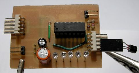
Project: Water Watcher
Problem: My reverse osmosis filter that delivers drinking water has some sort of problem, in that it continously consumes water, even when the production tank is full. My thinking is the auto-shutoff valve has failed. Well, I could get another asv but whats the fun in that. The filter system has a pressure sensor in it, which disables the booster pump (100psi output) when the tank reads full, but the water supply is not controlled. I’ve been manually turning the water supply on and off to the filter, as well as unplugging the pump when the water is turned off. The second, perhaps larger problem is, my filter drains its brine (waste) water out a tube through the side of my house, rather than going down the drain. In the summer, I collect this water and use it for filling watering cans. In the winter, the water likes to freeze in the drain.

Goals: Design and fabricate a microcontroller operated filter management controller. The first goal will be to monitor the outdoor temperature. When the outdoor temp is safely above freezing, enable filter operation. The second goal is to monitor storage tank pressure. When the tank reads low, enable filter operation. This is so easy, I’m not sure why I haven’t started it yet.

Solutions:
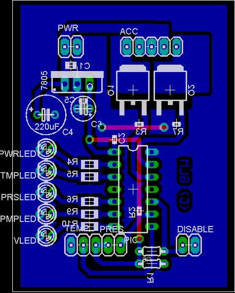
Goal number one; using as DS18B20 digital temperature transducer, monitor the outdoor temperature. A simple interrupt driven routine can sample the temperature every N amount of time. If the temperature is above freezing + 5 degrees (to account for any sensor accuracy problems), enable a register in the microcontroller, saying filter operation is allowed. When the temperature is below the set-point, disable filter operation. This should take five or ten lines of code.

Goal number two; using the pressure switch that is already part of my filter, sense the fluid level in the tank. The switch is normally closed, and opens when the storage tank is ‘full’. An interrupt driven routine will sample the state of this switch. When the switch is closed, an input pin on the microcontroller will read low, indicating the tank needs topping-off. The mcu can then set a register enabling operation of the filter.

The microcontroller in its idle loop, can monitor the state of the registers mentioned above, ANDing them together. When both registers are set to enable, the mcu will enable the booster pump and a solenoid valve (sprinkler valve) controlling the water. When either the temperature or pressure registers read disable, the AND will read a zero and filter operation will be suspended. Additional features could include a remote led status display, indicating filter status (temp high/low, pressure high/low, pump and water on/off). Another feature that would be handy is a change filter indicator, which times out every three months, indicating the need to replace the prefilters. I’m not sure how to do this, without including a real time clock, and that doubles the expense of this project. Of course, there are probably simpler means, like counting the oscillations of a 32khz crystal and just waiting for approximately three months worth of time to go by?

******
Project: Finishing the MAX1668 temperature sensing data logging clock.

I already have the clock and data logging working, but sort of lost interest when it came time to program some data analysis and reporting features, as well as make a PCB for the circuit, so the clock could be installed in an enclosure. So the clock has been sitting under my monitor shelf. Its kinda handy as it is, I use it as a desk clock and local temperature readout.

Goals; Add some menus to review logged data. Daily average temp readout for each channel. Daily and all-time min and max memory for each channel. Temperature trend indicator (rising / falling). Historical data like lowest recorded temp (what date, time and channel), highest recorded temp (date, time, channel).

******
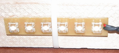
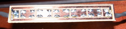
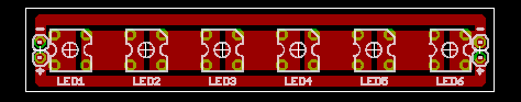
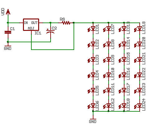
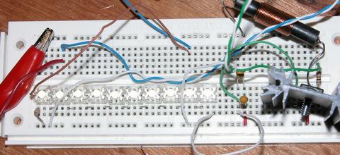
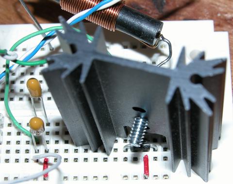
Project: High end kitchen counter lights.

Goals; The lighting concept works… scaled up, the lights should provide ample light for task lighting. I need to build (or find) a power supply for the lights (~36v, 1a). I also need to start on the controller. Some features I want to have:

Using a capacitive proximity switch (qprox). Touching the fixture should change the state of the lights with light sensing intelligence. If the room is dark and you request the lights to turn on, they ramp up to perhaps 25% output, as a night-light mode. Another touch of the fixture would bring them to 100%. If the room is light and you request a turn on, they would ramp up to 100%. Additionally, if the room goes from light to dark (like the main lights were turned out at night), ramp down to 25% output and remain on for an hour or so, as a night light. If the main lights are off and the fixture is off, should the main lights come on, sense this and automaticly come up, ramping up to 100%. If the room is light, and the fixture is on, touching the fixture shall turn the fixture off. If the room has gone from light to dark and you touch the fixture with-in N minutes, the lights should turn off, after N mintues, if the fixture is still on and another touch is detected, ramp to 100% output.

All that sounds like a lot, but it should easily be handled by a microcontroller and maybe a few dozen lines of code, all those conditions are simple binary logic comparisons.

******
Well, that was a good start, got a few ideas down – still too many in the ‘ol brain, so there will be a part two shortly!

Welcome Back

Welcome back everyone… or at least, welcome back to myself.

I took the week between Xmas and Newyear off, and caught up on some non-electronics.

I have a few things in the skunk works, not that they’re really secret or anything, but I’m reserving a lot of details until the projects are farther along – hoping to write up some articles rather than just short posts in the blog.

For now, here’s a few pictures:

smps switch mode power supply buck converter step-down hv9910

switch mode power supply … this circuit is a buck converter or step-down regulator … it’s programmed to supply 500mA into a load (constant current regulation). With my load (seen below), I measured about 90% effiency.

warm white nichia jupiter luxdrive moon power led

four warm-white Luxdrive IO Moon leds, two watts each, using Nichia Jupiter leds (click for larger picture)

same leds above, lit up

Booster Board

Here are a few pictures of my boost-mode converter, originally posted in my thread on linear1.

switch mode power supply boost step-up breadboard
breadboard with 10 led series string, and boost converter circuit


just the boost converter circuit – here you see the output capacitors, the rectifier (buried under the heatsink), the switch (on the other side of the heatsink) and the inductor

pwm waveform
this is the pwm pulsetrain from the PIC … only 10khz and already not quite square – it looks a lot worse at 20khz

out current waveform
output current measured across a 10 ohm resistor, with a basic choke filter on the output from the converter.