TPS61040

Most of the applications for LEDs I’ve run into require a lower than supply bias voltage for the LEDs. This situation is fairly easy to deal with, you can use a current limiting resistor, a linear regulator, or in high power applications, a step-down or buck converter.

However, occasionally, it may be beneficial to have a rather high LED bias voltage, even with a low supply voltage. For example, in small battery powered applications, rather than run your LEDs in largely parallel configurations (which has many drawbacks), you can string the LEDs together in a large series string, and then parallel those strings if need be.

Enter the TPS61040 from Texas Instruments. The TPS61040 is an integerated high efficiency step-up or boost converter. It is a integerated converter rather than a controller, because it contains both the power switch and the feedback circuitry. This means a very simple design is all that’s required to make it work – and in my opinion, the smaller the part count, the better.

tps61040 step-up boost converter smps led driver

There is my schematic, which provides for a variable voltage constant current “LED Driver”. LED current is programmed by resistors R1 and R2, which are connected in parallel. Inductor L1 is a small 10uH inductor, and D1 is a ‘standard’ schottky diode. C1 and C2 are low ESR ceramic capacitors, with an X7R rated dielectric. The chip itself, IC1 is an amazingly small SOT23-5 package surface mount IC. The rest of the components are also surface mount, both for space savings and laziness, as I hate drilling holes. I was out of SMT schottky diodes at the time I drew this, so D1 is a 2.8mm by 7mm DO41-7 package. C1 can be a 10 or 16 volt cap, C2 should be rated at the output voltage plus a safety factor (for dealing with ripple). L1 should be sized to handle the current demands of the circuit – I just went with 1.6 amps since it was cheap.

tps61040 pcb layout artwork

The layout is about 20mm square. My intended application is for lights inside a “shadowbox” style picture frame. I want a small string of white LEDs powered by some cheap AA batteries. I’m out of PCB developer right now, so no PCB fab this weekend. Once I get some more in, I’ll share the finished product with everyone, as well as some pictures of my cheezy art project.

If anyone should want full resolution layout or pcb artwork, just hit the contact justdiy button, over in the right hand sidebar.

LED Drivers

One of the “quests” I have been on lately, is to find an optimal solution for driving Light Emitting Diodes. I want a solution that balances three key needs; efficiency, flexibility and cost. Efficiency and cost have a direct linear relationship it seems – the more efficient something is, the more it will cost. Flexibility seems to have an inverse relationship with efficiency – the more flexible a solution is the less efficient.

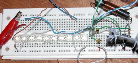
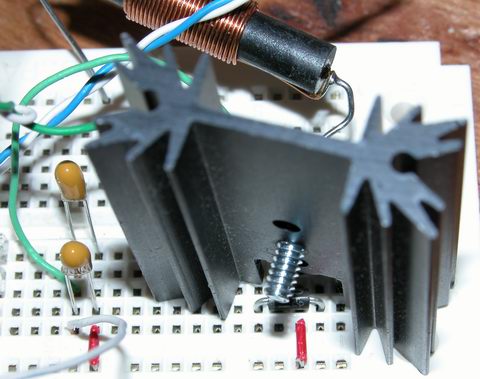
For example, take these three basic “led driver” prototype circuits:
led driver prototypical schematics

Starting off, the plain ‘ol resistor. The only strength this solution has is cost. It is neither flexible nor efficient. That is not to say an optimally designed solution will not see decent efficiency using a plain resistor, the designer needs to closely match the LEDs forward voltage to that of the supply. Now as long as the supply voltage never changes and the attributes of the LEDs never change, the resistor will do its job, limiting current. However, if the designer has limited control over the supply voltage, the resistor’s efficiency is down the drain. Because a resistor is a passive component, it cannot react at all to any changes – therefore the designer needs to specify a resistor for the maximum anticipated supply voltage, which results in sub-optimal light output during periods when the supply voltage is less than maximum. Low efficiency equates to wasted power and excessive heat. In summary, the plain ‘ol resistor is the easiest ‘driver’ to build, using simple arithmetic, the value and capacity of the resistor can be calculated; R = (Vsupply – Vleds) / Ileds and P = Ileds ^ 2 * R.

Next, we have the humble linear regulator. I chose the LM317, which is widely available and very inexpensive. The strengths of linear regulation are two fold. First, linear regulation provides a wide degree of flexibility. Secondly, linear regulation provides a very low cost. Two out of three is not bad, but the last one is the kicker. Linear regulation is terribly inefficient. A linear regulator configured for constant current mode is going to consume (dissipate) almost as much power as the load it is regulating. This means a 5 watt LED load is going to have the regulator dissipating an additional 5 watts. So using linear regulation in your design, the power source must deliver 10 watts to give yeild 5 watts of power for the lights, and this is an optimistic 50% efficiency – National Semiconductor gives the LM317 something like 43% efficiency! In summary, the linear regulator is marginally more complex than using a simple resistor, and about as easy to design. A single equation gets us the value of Rs, the current sense resistor; Rs = 1.25 / I.

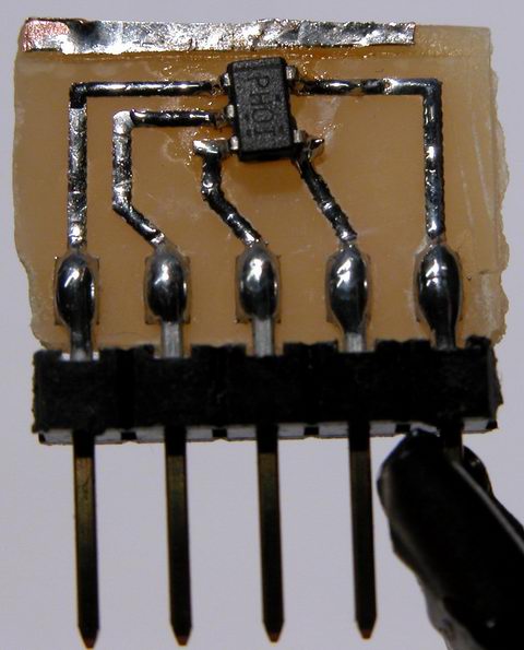
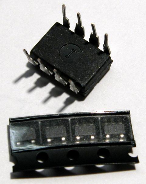
Next we have the compound, pre-made group of devices that I call switchmode drivers. The switchmode driver is a ‘black box’, in its simplest form, offering four leads, two inputs, two outputs. Drivers are available in two primary configurations; step up (boost topology) and step down (buck topology). Both configurations excel in efficiency. While efficiency alone is a good enough reason for some designs, such as battery powered applications, the switchmode drivers also offer a limited degree of flexibility. The negative aspect of a switchmode driver is cost. Prices for switchmode drivers start in the neighborhood of $10 and top out around $60. Flexibility in switchmode drivers is usually in the form of allowable ranges. For example, a step down driver may allow an input range Vout + 2V to 36V. That same driver may also have a range on the output, for example 3V to 28V. The biggest drawback to the switchmode driver is the lack of adjustable drive current. In general, a switchmode driver has to be purchased from the factory with a pre-programmed drive current. While this is fine for most designs, it is not optimal. In summary, the switchmode driver offers excellent efficiency, often times better than 85%, but it offers this efficiency with great cost and limited flexibility. There is no math required to design using a switchmode driver, you just have to pick one that matches your supply voltage and LED current needs.

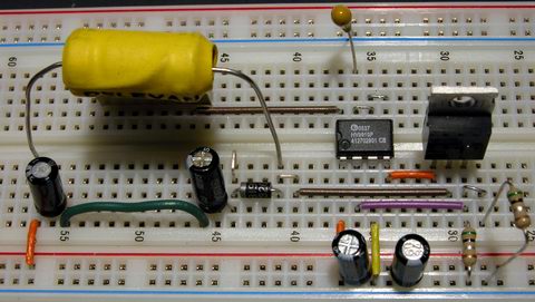
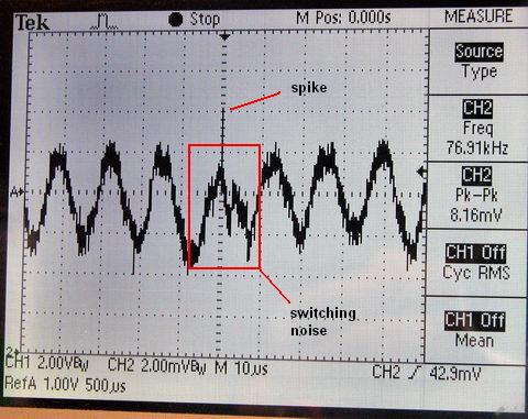
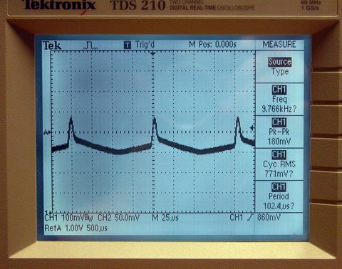
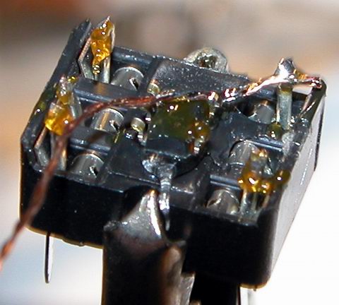
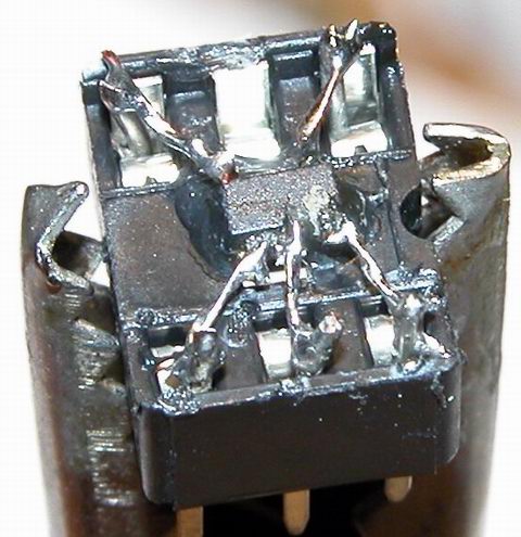
The last driver I will briefly touch on, saving the details for next time, is the home-brew or DIY switchmode driver. In kit form, this driver satisfies all three of my design goals. Decently low cost (less than $10 in parts), high efficiency (more than 80%) and good flexibility (I control the programming). Of course, there are some drawbacks; some of the parts are hard to find, there is a LOT of math involved and due to high frequencies and currents, careful circuit layout needs to be observed.

Another technology I will mention, but have not researched much (it is truly bleeding edge in the industry) is something called SEPIC. The acronym stands for Single Ended Primary Inductor Converter. It is a technology pioneered by Maxim and combines the abilities of both a step up and step down regulator into a single design. The ‘old fashioned’ buck-boost regulator of yesteryear do their voodoo by internally generating very high voltages, and using the positive rail as a low side reference for the load … that design has some very hard limits and is also rather inefficient. SEPIC hopes to solve these problems with a radically different and more complex design. SEPIC offers a power supply that with ultimate in flexibility – there need be no correlation between input voltage and output voltage. Want to run 15 volts of LEDs off a 3.7 volt lithium battery, no problem. Want to run 11 volts of LEDs off an automotive supply that varies between 11 and 15 volts, no problem.

I have more to write on this subject – my next post on this subject will sum up my experience in designing switchmode power supplies and share some designs the reader may find useful.

Dead Bug, Revisited

My previous dead bug attempts were just that, dead bugs … although the mounting method was successfull, it was really difficult to get the chip to stay put – the heat from soldering the connections melted the glue and the thing was sliding around.

So, I made up some PCB layouts for an SOT adapter, allowing me to solder the chip properly, and still provide something I can use easily in a breadboard. This is what I came up with:

tps61040 dc-dc converter switch mode power supply boost step-up

Not the cleanest example of my work, I admit to the fact it looks pretty awful. But it does work well. It is just a simple SOT-23-5 transistor pad layout, expanded to 0.100″ pitch pads. To the big pads, I solder the short side of a molex C-Grid pin header, and then solder the IC to its pads. The C-Grid pins plug perfectly into a breadboard. The whole thing is about the size of a nickel.

Ok, so now that I have the IC in a managable package, what does it do? The IC is a Texas Instruments TPS61040 step-up dc-dc converter. You feed it a low voltage (3 to 6v), and it produces a high voltage (3 to 28v). The IC contains almost all the parts of a switch mode power supply, including the switch itself.

switch mode power supply texas instruments tps61040

Add a hand wound inductor, a few caps and a schottky diode, and I have a complete SMPS. The 040 offers a few neat features, including analog and digital dimming support, automatic softstart to limit inrush current, open load detection, and very very low standby / no load currents. For my experiments, I decided to power eight white piranha LEDs at 50mA (the 040 can handle up to 400mA). My power source was two 1.5 volt alkaline batteries, connected in series.

I was able to run the leds for a few hours until my super cheap “Shazam” brand batteries gave out. I’m sure with a proper set of four NiMH batteries, the LEDs would run for a long time.

My next experiment will be to run a string of power leds using this converter… say four 2 watt jupiters (well, at 400mA, I won’t achieve quite 2 watts). I need to get a proper inductor and a larger output capacitor, to handle the much increased load.

Welcome Back

Welcome back everyone… or at least, welcome back to myself.

I took the week between Xmas and Newyear off, and caught up on some non-electronics.

I have a few things in the skunk works, not that they’re really secret or anything, but I’m reserving a lot of details until the projects are farther along – hoping to write up some articles rather than just short posts in the blog.

For now, here’s a few pictures:

smps switch mode power supply buck converter step-down hv9910

switch mode power supply … this circuit is a buck converter or step-down regulator … it’s programmed to supply 500mA into a load (constant current regulation). With my load (seen below), I measured about 90% effiency.

warm white nichia jupiter luxdrive moon power led

four warm-white Luxdrive IO Moon leds, two watts each, using Nichia Jupiter leds (click for larger picture)

same leds above, lit up

Booster Board

Here are a few pictures of my boost-mode converter, originally posted in my thread on linear1.

switch mode power supply boost step-up breadboard
breadboard with 10 led series string, and boost converter circuit


just the boost converter circuit – here you see the output capacitors, the rectifier (buried under the heatsink), the switch (on the other side of the heatsink) and the inductor

pwm waveform
this is the pwm pulsetrain from the PIC … only 10khz and already not quite square – it looks a lot worse at 20khz

out current waveform
output current measured across a 10 ohm resistor, with a basic choke filter on the output from the converter.

Down to the wire

Well well well – time is running short, and only one of three outstanding orders has been filled.

The boost converter is coming along – I’ve made refinements to the software that offer some good features and better performance. However, I think my hardware design needs more work… and for that, I need parts!

Out of desperation, I visited Satan’s Lair aka Radio Shack and was pleasantly surprised to find some of the items I had been missing. I managed to get a 2a 100uH inductor and (only) two 1uF tantalum capacitors. Having a proper inductor really made a big difference in the output of my boost converter – it sails to the limit I set for 25mA without any problems now, the old hand wound torrid would struggle to get past 20, begrudgingly giving me 25mA along with a lot of HEAT. The real test will be tonight – I’m going to wire up some power resistors as a test load and see if my boost converter can give me half an amp. Why 0.5A you ask? I need half an amp to drive my Moon LEDs at their fully rated 2w power.

The boost converter was originally intended to be a power supply for two parallel strings of LEDs, installed as under cabinet lights.

The lights themselves will be made of aluminum C channel and plexiglas, using 2 watt IO Moon led modules, spaced evenly along the length. I’m not sure what the spacing should be – there is probably some math that would tell me, based on viewing angle and what not. Since these are a prototype, I’m going to ballpark the spacing, so the LEDs I have (4) are spaced evenly across the length of the countertop. I need to take a few covert measurements to figure out how long the channel needs to be. I managed to find a local source, and have secured sixteen feet of aluminum C channel. This stuff has a chunky 1/8″ wall thickness and 1.5″ x 0.5″ outside measurements… combined with a little Arctic Silver, this should be an awesome heat sink for the LEDs.

Pictures to come shortly!

PIC Based Boost Regulator

I have a running thread over at the linear1 forums, chronicling my experiences with building a digital switch mode power supply.

Here is a re-cap of where I’m at now.

The boost converter is a coil, a few capacitors, a diode and a darlington transistor. The PIC manages switching the transistor. Switching is done autonomously by a PWM generator inside the PIC. Constant current regulation is achieved by measuring the voltage drop across a 100 ohm resistor. The voltage is measured approximately 5000 times a second, and the pwm duty cycle is adjusted up or down, depending on the read voltage’s deviation from the set voltage. With a 100 ohm resistor, the math works out real easy – 100mV is 1 mA. Of course, 100 ohms will not work for a heavy current load – so I will have to reduce it to 1 ohm or 0.5 ohms, which changes my math a little, but no big deal.

oscilloscope digital tds 210 Tektronix current ripple

I’m having problems with noise in the output current corrupting the A2D input to the pic. Better capacitors and a real ‘power’ inductor are on order and should arrive wed or thur. When they get here, I will rebuild this project so I don’t have, for example, a 12″ piece of wire connecting my switch to my pwm output.

PIC Based Boost Converter

The idea of using a PIC microcontroller as a replacement for the analog circuitry of a smps controller was originally suggested to me by SurJector over on the linear1.org forums.

Originally I felt the topic was over my head. I also dismissed it because I thought it added unnessecary complexity to an already difficult to understand process. However, as I read more about how switch mode power supplies and dc/dc converrts worked, I realized that using a PIC as the brain was indeed a good idea, and very cutting edge. ‘Digital’ switch mode power supplies are just now starting to ‘pop up’ in the industry, with all the current “all in one” controllers still relying completely on analog.

As I understand it, a digital controller offers the potentional for great efficiency, by adjusting the operating frequency of the switch dynamicly with the load. I’m not sure how that all works yet, but I have a few other things in mind, related to using these converters in the field of solid state lighting. Firstly, I like the idea of being able to digitally controll the output current to the load. Instead of having to dim a bulb using PWM, which is very non linear, I can instead dim a bulb using current mode control… using whatever interface suits me. Secondly, a digital controller could be integerated into a larger project, an illumination manager. For example, combine the dc/dc conversion routine with a routine reading a thermistor – monitor your bulb temp and dynamicly vary the current to keep it at a safe level. Another possibility – with a digital processor monitoring the current draw of the load, a faults such as shorted or open diode could be detected and an alarm condition set – in addition to reducing the current to compensate, a small indicator led could light up – “Check Lights”.

I have some pictures and schematics to share when I’m back home – more to come!

Dead Bug

In addition to my new moons, I also received some sample DC/DC converters from Texas Instruments. In order to experiement successfully with this new switch-mode power supply, I need to be able to use it on a breadboard.

I could have drawn up and made my own ‘breakout board’ pcbs. I could have bought commerically made ‘experimentor’ boards. But I decided to use the cheap and fast “dead bug” method instead. I used a little dab ‘o hot glue and a 6-pin DIP socket to convert my SOT-23 packaged device into something I can now use with a bread board.

The jumper wires I used are two strands of wire for a 24ga stranded wire. I twisted the two strands together for a little more strenght. I also used some 24 ga solder wire to extend up from each spring in the socket, rather than soldering to the spring itself. The hard part with this process, and I think I’ll look to epoxy instead of hot glue next time – as I heated the part during soldering, it would soften the glue, and the part would move! In the last picture, it looks like there are some solder bridges, but there are not – that crap between the pins is just debris from my parts cleaning brush … looks like its time for a new brush!

More on the TPS61040 and what it does a bit later.

Enjoy:
dead bug solder tps61040 sot-23 smd
6 pin dip socket

dead bug solder tps61040 sot-23 smd
cut tape string of four converters

dead bug solder tps61040 sot-23 smd
single converter sitting on an 8 pin DIP package IC

dead bug solder tps61040 sot-23 smd
converter glued to ic socket

dead bug solder tps61040 sot-23 smd
starting the soldering process

dead bug solder tps61040 sot-23 smd
finished soldering